Selecting the correct vibration damper requires matching inertia ratio (typically 0.6 to 1.2 times crankshaft inertia), stiffness characteristics (natural frequency placement outside operating range), and damping coefficient (elastomer for tuned absorption or viscous for broadband control) to the engine’s torsional vibration profile—validated through Holzer calculations and confirmed by dynamometer testing.
For design engineers, powertrain developers, and technical buyers, understanding the engineering principles behind crankshaft vibration damper design is essential for specifying components that protect engine durability while meeting cost and packaging constraints. The vibration damper is not a commodity component—it is a precisely tuned dynamic system whose characteristics must be matched to the engine’s unique torsional signature. This reference guide provides the technical specifications and selection methodology needed to specify dampers correctly, whether for new engine development or replacement applications.
Fundamental Principles: Torsional Vibration Physics
Before selecting any engine vibration damper, engineers must understand the physical phenomenon they are controlling. Torsional vibration is the angular oscillation of a rotating shaft superimposed on its mean rotational velocity. In internal combustion engines, this oscillation is caused by the periodic nature of combustion—each cylinder firing creates a torque impulse, and between firings, the crankshaft unwinds.
The critical danger occurs when the frequency of these impulses aligns with the crankshaft’s natural torsional frequency—a condition called resonance. At resonance, vibration amplitudes can increase by factors of 10 to 50 compared to off-resonance operation, generating stresses that rapidly exceed the crankshaft’s fatigue endurance limit. A torsional damper for crankshaft applications works by adding mass and damping to the system, shifting natural frequencies and absorbing vibrational energy.
Damper Types: Technical Comparison
Two primary damper technologies dominate the market: elastomer (rubber) and viscous (silicone fluid). Each offers distinct technical characteristics suited to different applications.
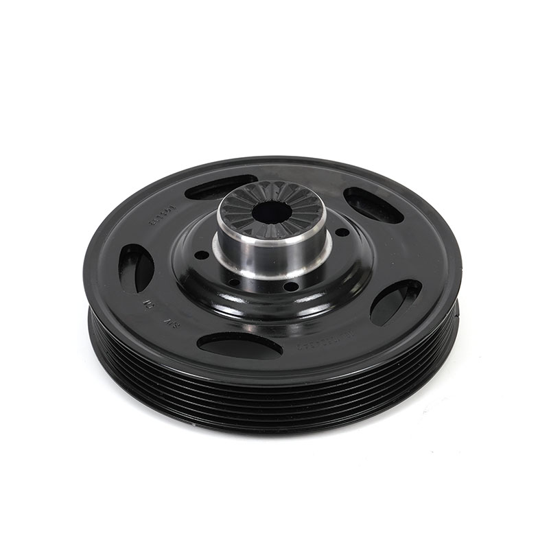
Elastomer (Rubber) Dampers: Technical Specifications
Elastomer dampers consist of an inertia ring connected to the hub by a rubber element. The rubber acts as both a spring and a damper. Key technical parameters include:
- Tuned Frequency: The damper provides maximum damping at a specific frequency determined by rubber stiffness and inertia ring mass. This frequency is typically set to target the engine’s dominant critical order—often the second or fourth order for four-cylinder engines, third or sixth for six-cylinder engines.
- Damping Coefficient: Elastomer damping is frequency-dependent, with the rubber’s loss factor (typically 0.1 to 0.3 for natural rubber, 0.2 to 0.5 for synthetic compounds) determining energy dissipation.
- Temperature Sensitivity: Rubber stiffness changes with temperature. The modulus of natural rubber increases approximately 15 percent from 20°C to 80°C; synthetic compounds like HNBR maintain more stable properties across temperature ranges.
- Service Life Indicators: Elastomer dampers degrade through heat aging and cyclic fatigue. End-of-life is typically indicated by rubber hardening (Shore A increase of 10 points or more), cracking reaching the bond line, or visible de-bonding.
Viscous (Silicone Fluid) Dampers: Technical Specifications
Viscous dampers feature an inertia ring enclosed in a housing filled with high-viscosity silicone fluid. Damping occurs through fluid shear as the inertia ring oscillates. Key technical parameters include:
- Broadband Damping: Unlike elastomer designs, viscous dampers provide effective damping across all frequencies, making them ideal for engines operating across wide RPM ranges.
- Damping Coefficient: Determined by fluid viscosity, inertia ring geometry, and operating clearance. Silicone fluid viscosity typically ranges from 10,000 to 100,000 centistokes at 25°C, selected based on damping requirements.
- Thermal Stability: High-quality silicone fluids maintain stable viscosity from -40°C to 200°C, ensuring consistent damping across extreme operating conditions.
- Service Life Indicators: Viscous damper failure typically begins with seal leakage or fluid shear degradation. Fluid viscosity loss exceeding 20 percent from original specification indicates end-of-life.
Technical Comparison: Elastomer vs. Viscous Dampers
| Parameter | Elastomer Damper | Viscous Damper |
|---|---|---|
| Damping Bandwidth | Narrow (tuned to specific frequency) | Broad (effective across all frequencies) |
| Peak Temperature Limit | 100-130°C (depending on compound) | 200°C (silicone fluid stability) |
| Low-Temperature Performance | Rubber hardens below -20°C | Viscosity increases gradually, remains functional |
| Cost | Lower (simpler construction) | Higher (precision sealing, fluid filling) |
| Typical Service Life | 5,000-10,000 hours (duty dependent) | 10,000-20,000 hours (continuous duty) |
| Failure Mode | Gradual (visible rubber degradation) | Sudden (seal failure) or gradual (fluid shear) |
In-Depth: Technical Specification Parameters for Damper Selection
For engineers specifying a crankshaft vibration damper solution, the following technical parameters must be defined to ensure proper matching to the engine system. This section provides the detailed methodology used by damper engineers during the design phase.
Inertia Ratio Calculation: The inertia ratio—the ratio of damper inertia to crankshaft system inertia—is the primary tuning parameter. For most applications, target inertia ratios fall between 0.6 and 1.2. Lower ratios (0.4-0.6) are used when packaging constraints limit damper size; higher ratios (1.0-1.5) provide greater vibration reduction but increase rotational mass and cost. Calculation methodology:
Damper Inertia (J_d) = Target Inertia Ratio × Crankshaft System Inertia (J_c)
Crankshaft system inertia includes the crankshaft itself plus flywheel and any attached components. For a typical six-cylinder diesel engine, total system inertia might range from 0.5 to 2.0 kg·m², resulting in damper inertias from 0.3 to 2.4 kg·m².
Stiffness and Tuning Frequency: For elastomer dampers, rubber stiffness (K_r) determines the damper’s natural frequency. The target is to place the damper’s natural frequency at the critical engine order that produces the highest torsional amplitudes. The relationship is:
Damper Natural Frequency (f_d) = (1/2π) × √(K_r / J_d)
This frequency must be expressed as an engine order: Engine Order = f_d × 60 / Engine RPM at Critical Speed
For example, a damper tuned to 300 Hz for an engine with a critical speed at 3,000 RPM would target the 6th engine order (300 × 60 / 3,000 = 6).
Damping Coefficient Determination: The damping coefficient (C) determines how effectively the damper dissipates energy. For elastomer dampers, the loss factor (tan δ) is typically 0.1 to 0.4. For viscous dampers, damping is characterized by the fluid viscosity and geometry. The optimum damping coefficient for a given application is determined through iterative analysis, with typical values resulting in 60-80 percent reduction in peak torsional stress at the critical engine order.
Thermal Management Specification: Damper operating temperature directly affects durability. Elastomer dampers generate heat through hysteresis—each cycle of rubber deflection converts some mechanical energy to heat. Viscous dampers generate heat through fluid shear. Engineers must specify:
- Maximum Operating Temperature: For elastomer dampers, continuous operation above 100°C accelerates aging; peak temperatures above 120°C risk thermal runaway. For viscous dampers, continuous operation up to 150°C is acceptable with proper fluid formulation.
- Heat Dissipation Path: The damper’s mounting interface with the crankshaft provides the primary heat path. Designers must ensure adequate thermal conduction through the hub to the engine’s lubrication and cooling systems.
- Ambient Temperature Range: Cold-start conditions affect elastomer stiffness and fluid viscosity. Specify the expected ambient range to ensure proper material selection.
Technical Documentation and Cross-Reference Capabilities
For replacement applications, accurate Technical Specifications for Crankshaft Dampers and cross-reference data are essential. A capable Supplier provides:
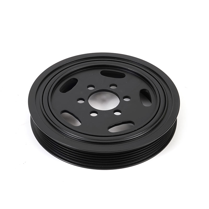
- OEM Interchange Numbers: Cross-reference data linking aftermarket part numbers to original equipment manufacturer numbers.
- Dimensioned Drawings: Critical dimensions including hub bore diameter, pilot diameter, bolt pattern, overall height, and outside diameter.
- Material Specifications: Hub material (gray iron, ductile iron, aluminum), rubber compound (natural, HNBR, silicone), or fluid type and viscosity.
- Performance Specifications: Inertia value, dynamic balance tolerance, stiffness rating, and damping coefficient.
As a Manufacturer with integrated engineering and production capabilities, we maintain comprehensive technical documentation for all damper types. Our customizable engineering process begins with detailed engine parameter analysis, using proprietary calculation models to determine optimal inertia, stiffness, and damping values. For OEM customers, our OEM/ODM capabilities include full design ownership and validation support. For aftermarket distributors, our Supplier and Wholesaler channels provide access to complete technical specifications, cross-reference data, and application guidance to ensure customers receive the correct component for their specific engine platform.
FAQ: Technical Specifications and Selection
What technical data do I need to provide to have a custom vibration damper designed?
For a customizable damper design, provide engine specifications: cylinder configuration (4, 6, 8, etc.), firing order, bore and stroke, rated power and torque, maximum RPM, crankshaft geometry (main journal diameters, throw dimensions, number of main bearings), flywheel inertia, and any packaging constraints (maximum OD, available depth, mounting interface details).
How do I determine if I need a rubber or viscous damper for my application?
Choose elastomer (rubber) for applications with relatively stable operating RPM ranges, cost sensitivity, and where visible wear indicators are desired. Choose viscous for variable-speed applications, continuous high-load duty, extreme temperature environments, or when maximum broadband damping is required. Marine propulsion and generator applications typically favor viscous; on-highway truck engines often use high-grade elastomer.
What is the acceptable vibration amplitude after damper installation?
Acceptable torsional vibration amplitudes vary by engine design. General guidelines: below 0.2 degrees angular amplitude for sustained operation is excellent; 0.2-0.4 degrees is acceptable for most production engines; above 0.5 degrees requires investigation and may indicate damper degradation or mismatch. These values should be measured at the damper location using appropriate instrumentation.
How often should vibration dampers be replaced in industrial applications?
Replacement intervals depend on application and damper type. For elastomer dampers: 5,000-8,000 operating hours in continuous-duty industrial applications. For viscous dampers: 8,000-12,000 hours. For standby generators with low hours, time-based replacement at 8-10 years is recommended regardless of operating hours due to rubber aging and seal degradation.
What cross-reference information is needed to identify the correct replacement damper?
Required information includes engine make and model, OEM part number (if available), engine serial number range, damper dimensions (overall diameter, hub bore, pilot diameter, bolt pattern), and visual identification of damper type (rubber visible or sealed viscous case). A qualified Supplier should be able to cross-reference these parameters to provide the correct replacement.
How do I verify that a replacement damper meets OEM specifications?
Request the supplier’s technical data sheet showing inertia value, dynamic balance tolerance, and material specifications. For critical applications, ask for test reports from an accredited laboratory verifying that the damper’s performance matches original design parameters. Suppliers with IATF 16949 certification and in-house testing capabilities can provide this documentation.
Sources: SAE J2481 Testing of Viscous and Elastomeric Crankshaft Dampers; Den Hartog, J.P. (1985). Mechanical Vibrations; Nestorides, E.J. (1958). A Handbook of Torsional Vibration, Cambridge University Press; International Organization for Standardization ISO 1940-1 Balance Quality Requirements.