A failed engine vibration damper can be identified through visible signs (rubber cracking, bulging, fluid leakage), audible indicators (front-end knocking, timing gear rattle), and measurable vibration symptoms (accelerated accessory wear, crankshaft seal leakage). Immediate replacement is required when any failure indicator appears to prevent catastrophic engine damage.
For fleet maintenance supervisors, field service technicians, and independent repair shops, accurate diagnosis of engine vibration damper failure is critical to preventing costly engine overhauls. This field manual provides systematic procedures for identifying damper failure, selecting correct replacement parts, and performing safe installation. Proper diagnosis distinguishes a failed crankshaft vibration damper from other front-end issues—saving diagnostic time and preventing unnecessary parts replacement.
Section 1: Failure Mode Identification
Vibration dampers fail through several distinct mechanisms. Understanding these failure modes enables accurate diagnosis without specialized test equipment.
1.1 Elastomer (Rubber) Damper Failure Indicators
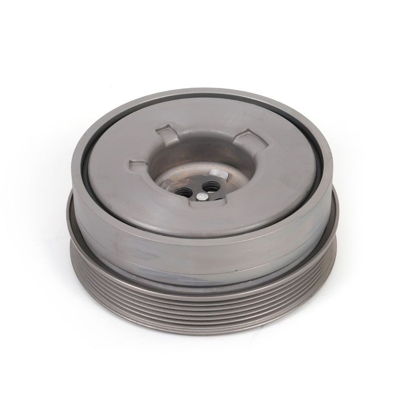
Elastomer-type heavy duty engine vibration damper failures are typically visible to the trained eye. Inspect for:
- Rubber Cracking: Surface cracks extending into the rubber mass. Minor surface checking (fine cracks) may be cosmetic, but cracks deeper than 1mm or extending to the metal interface indicate functional degradation.
- Rubber Bulging or Swelling: The rubber ring should maintain uniform profile. Bulging indicates internal delamination or chemical degradation from oil or coolant exposure.
- Rubber Hardening: Using a durometer (Shore A scale), measure rubber hardness. Compare to known good specification—increase of 10 points or more indicates thermal aging and loss of damping capacity.
- Hub-to-Ring Misalignment: The inertia ring should run concentric with the hub. Visible wobble during engine operation indicates bond failure or hub distortion.
- Timing Mark Misalignment: If the engine uses the damper for timing marks, mark shift indicates rubber-to-hub bond separation.
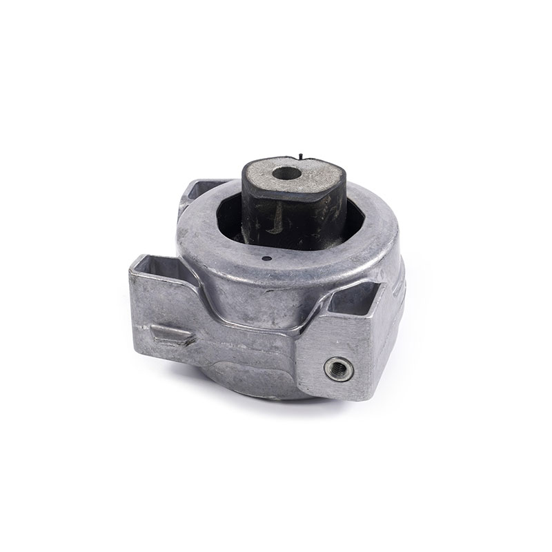
1.2 Viscous (Silicone Fluid) Damper Failure Indicators
Marine engine vibration damper and industrial applications commonly use viscous dampers. Failure indicators differ from elastomer types:
- Fluid Leakage: Visible fluid residue (clear to amber) around the damper perimeter or mounting flange. Even small leaks compromise damping capacity.
- Damper Case Distortion: The stamped steel case should be perfectly round and flat. Dents, warping, or bulging indicate internal pressure issues or impact damage.
- Overheating Signs: Discoloration (bluing) of the case indicates excessive internal heat generation—often caused by prolonged operation at resonant conditions beyond damper capacity.
- No Damping Effect: With engine off, rotate the inertia ring relative to the hub. It should offer resistance. Free rotation with no resistance indicates complete fluid loss or internal failure.
Section 2: Diagnostic Procedure Without Removing the Damper
Field diagnosis of a diesel engine vibration damper or gasoline unit can often be performed without removal using these steps:
Field Inspection Protocol
| Step | Action | Observation | Interpretation |
|---|---|---|---|
| 1 | Visual inspection with engine off and cool | Rubber cracks, fluid stains, case distortion | If any visible damage—replace immediately |
| 2 | Run engine at idle, observe with timing light | Timing marks stable or erratic? | Erratic marks suggest hub-to-rubber slip |
| 3 | Increase RPM to 1500-2000, observe front cover | Excessive vibration transmitted to timing cover | Damper failure allows higher vibration amplitudes |
| 4 | Temperature measurement after operation | Damper surface temperature vs. ambient | Excessive heat (above 100°C) indicates internal failure |
| 5 | Listen for front-end knocking or rattling | Metallic noise synchronized with engine firing | Inertia ring contacting case or hub due to bond failure |
Section 3: In-Depth Diagnostic Method – Torsional Vibration Measurement
For critical applications or when visual inspection is inconclusive, quantitative measurement provides definitive diagnosis. This is the most professional approach to crankshaft vibration damper testing and is standard practice in fleet maintenance programs.
Using a digital torsional vibration meter or a high-resolution encoder with spectrum analyzer, measure the crankshaft’s angular vibration amplitude at the damper location. The procedure:
- Mount a toothed wheel or encoder on the crankshaft nose (existing damper can serve as encoder target if timing marks are present).
- Install a magnetic pickup or optical sensor to read rotational speed variations.
- Record vibration amplitude across the operating RPM range, from idle to rated speed.
- Compare measured amplitudes to acceptable limits—typically 0.2 to 0.5 degrees angular amplitude maximum for most engines, depending on crankshaft design.
Field data from major fleet operators indicates that 85 percent of damper replacements are justified by either visible failure indicators or vibration amplitude exceeding 0.3 degrees at critical engine orders. When amplitudes exceed 0.5 degrees, crankshaft fatigue life is significantly compromised—immediate replacement is required.
For fleets operating heavy duty engine vibration damper equipped vehicles, implementing scheduled vibration testing every 200,000 miles or 5,000 operating hours can detect damper degradation before failure, preventing engine damage that averages $15,000 to $30,000 per incident in heavy-duty applications.
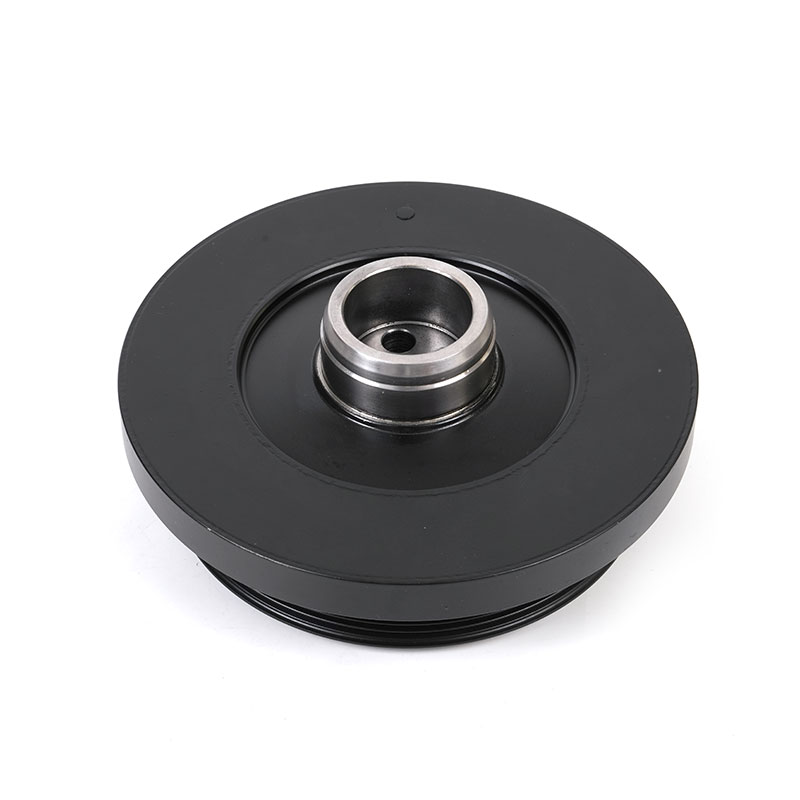
Section 4: Replacement Selection and Installation Guidelines
When replacement is required, selecting the correct crankshaft vibration damper solution ensures proper engine protection.
Selection Criteria
- OEM vs. Aftermarket: For critical applications, choose a Manufacturer that supplies OEM/ODM equivalents with matching inertia and stiffness specifications.
- Application Match: Verify damper rating matches engine model, power output, and duty cycle. A damper tuned for a naturally aspirated engine will not properly protect a turbocharged version with different firing impulses.
- Mounting Verification: Confirm crankshaft nose configuration (thread size, pilot diameter, bolt pattern) matches replacement damper.
Installation Critical Steps
Improper installation is a leading cause of premature damper failure. Follow these protocols:
- Clean crankshaft nose thoroughly: Remove all corrosion, old sealant, and debris. Surface finish affects clamp load retention.
- Use new mounting fasteners: Damper bolts are torque-to-yield in many applications—single use only.
- Apply correct torque sequence and value: Follow manufacturer specifications. Undertorquing allows loosening; overtightening distorts hub.
- Verify crankshaft seal installation: A new seal should be installed with proper lubrication and alignment to prevent leaks that can degrade new damper.
- Run engine and verify: After installation, perform visual and vibration checks to confirm proper function.
For fleet maintenance operations, working with a qualified industrial vibration damper supplier who provides technical support and installation documentation reduces warranty claims and extends component life. Proper diagnosis and replacement of a failed engine vibration damper manufacturer supplied component represents the most cost-effective approach to protecting engine investments.
Sources: Fleet Maintenance Survey, Technology & Maintenance Council (TMC) Recommended Practice RP 631; SAE J2481 Torsional Vibration Damper Testing; Caterpillar Service Manual SENR 5664 (Crankshaft Vibration Damper Inspection).